Edge-Blackening
How to Specify Edge Blackened Optics
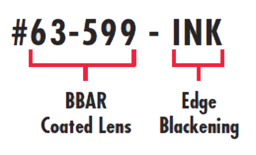
Any of our lenses with a diameter of 5mm or greater can be specified with blackened edges. To specify the blackening, simply append a –INK to the BBAR coated stock number. For example, to order a 10mm diameter, 10mm focal length, VIS 0° coated DCX lens with blackened edges, the stock number would be #63-599-INK.
Stray Light
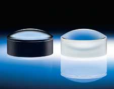
When integrating lenses into a multi-element system, a common limiting factor in overall performance is stray light. Stray light is energy outside of the clear aperture of an optical system that scatters off of the edges of an optical or mechanical component (Figure 1) and reaches the sensor in the form of noise (rather than signal). One successful method commonly used to reduce stray light within a system involves blackening the edges of the optics in the system.
Measuring BRDF
Scattered signals are typically quantified as scattered light power per unit solid angle, or inverse steradians. Scatter results are made more meaningful by normalizing the results by the intensity of light incident on the scatter source. This function is commonly referred to as the Bi-Directional Reflectance Distribution Function, or BRDF. A simplified equation of BRDF is the intensity ratio of reflected to incident light per solid angle. These measurements are taken by projecting a laser onto a surface at a fixed angle from the normal. A detector is then rotated about the point of scatter to record the change in irradiance as a function of angle (Figure 2).

Figure 1: Light reflected by an object outside FOV being scattered from the edges of a lens without edge blackening
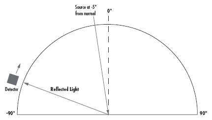
Figure 2: Detector recording irradiance as a function of angle
Figure 3 compares the results of such a test between one surface coated with edge-blackening ink, and the other uncoated ground glass to simulate the edge of an optic. The plot indicates an order of magnitude improvement in stray light reduction by edge-blackening. This improvement potentially save the need for expensive mechanical system baffling. With the detector close to -90° from normal, the percent of incident light recorded is near zero due to the high angle of incidence. At -5° the percent of incident light recorded is also 0%, due to the detector eclipsing the source. At +5° there is a spike due to the specular reflection (angle of incidence is equal to angle of reflection). The percent of incident light recorded then approaches zero as the angle of the detector again approaches 90° to the normal.
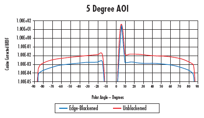
Figure 3: BRDF Plot of unblackened and blackened lenses
Results
Figures 4 and 5 illustrate an irradiance profile taken from a sensor imaging a point source through a lens. Figure 4 was generated by a standard optic while Figure 5 was generated with an edge-blackened optic. The effect of stray light as illustrated in Figure 4 is a higher noise floor that in effect washes out the image resulting in lower image contrast.
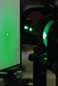

Figure 4: Conventional Results — Line profile of the irradiance distribution through the center of an imaging sensor where the lens edges are not blackened
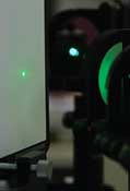
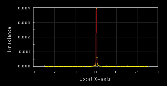
Figure 5: Edge-Blackened Results — Line profile of the irradiance distribution through the center of an imaging sensor where the lens edges are blackened
Edge-blackening, using RoHS compliant, solvent resistant ink is now available as a stock item for many Edmund lenses. Look for the INK suffix at the end of the stock number to indicate edge-blackening. In the case that it is not available as a stock item, edge blackening is also available through Optical Prototyping.
版權所有 © 2025 江陰韻翔光電技術有限公司 備案號:蘇ICP備16003332號-1 技術支持:化工儀器網 管理登陸 GoogleSitemap